A Pull Down Rig is Not Enough
What is a Pull Down Rig?
A pull down rig is a simple suspension test machine that applies vertical loads to a vehicle suspension. Pull down rigs can be used to check component clearances and calculate rudimentary ride rates.
The Limit of Pull Down Rigs
Pull down rigs are great for making quick suspension checks, such as checking for interference, but beware: Ride rate measurements on a pull-down rig can easily be 10% off (or more!) because the tires are not allowed to properly float and relieve their scrub forces. Yes, tire scrub forces influence vertical suspension rates.
Race cars are designed to corner, accelerate and brake as quickly as possible. So to get an accurate picture of what is really happening, you have to apply realistic cornering, tractive, and braking loads.
Consider these two simple examples illustrating the impact of cornering loads:
Effect of Cornering Loads on Vertical Loading
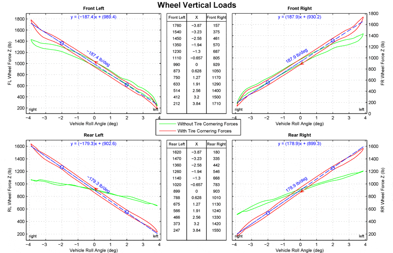
The figure below shows lateral weight transfer measurements with (red) and without (green) the introduction of tire cornering forces. The green traces could be obtained from a pull-down rig (or even a 7-poster), but for a given chassis roll angle, the measurements do not reflect what’s really happening. The red traces, measured on the Morse Measurements K&C rig and including proper tire cornering forces, tell a very different story:
As shown above, front and rear lateral weight transfer is not measured correctly unless lateral tire loads are applied. It is particularly noticeable in the rear of this vehicle, where over 300 lb of additional weight transfer comes from suspension jacking forces. Since total lateral weight transfer is dictated only by the cornering G’s and C.G. height, what we are seeing here is an effective change in roll stiffness when jacking loads are taken into account. The rear suspension is also shown to have significantly more load variation due to friction when properly loaded to simulate cornering. Only K&C testing will reveal this information.
Jacking force influence on weight transfer becomes even more pronounced when suspension rates become non-linear (due to bump-stop or coil-bind conditions) and when a vehicle is subjected to large aerodynamic down-force loads. And although this example only shows the lateral weight transfer characteristics, jacking will similarly influence longitudinal weight transfer during both throttle-on and braking.

Effect of Cornering Loads on Steer
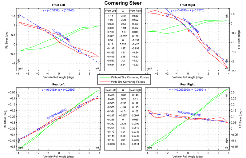
Cornering loads will also have a pronounced effect upon suspension geometry and vehicle trim. The figure below shows the steer angles at each corner of the vehicle, again with (red) and without (green) the introduction of tire cornering forces. Once again, the green measurements do not reflect what happens in real life. The red traces, measured on the Morse Measurements K&C rig and including proper tire cornering forces, provide a more accurate representation of vehicle steer trim while cornering:
As shown above, a roll oversteer set-up in the front suspension has degraded into severe roll understeer when tire cornering loads are taken into account. This clearly demonstrates the importance of the “C” (for Compliance) in K&C testing. It also raises questions about what else is happening to the suspension under load. Again, only K&C testing will reveal this information.

What is a Pull Down Rig?
A pull down rig is a simple suspension test machine that applies vertical loads to a vehicle suspension. Pull down rigs can be used to check component clearances and calculate rudimentary ride rates.
The Limit of Pull Down Rigs
Pull down rigs are great for making quick suspension checks, such as checking for interference, but beware: Ride rate measurements on a pull-down rig can easily be 10% off (or more!) because the tires are not allowed to properly float and relieve their scrub forces. Yes, tire scrub forces influence vertical suspension rates.
Race cars are designed to corner, accelerate and brake as quickly as possible. So to get an accurate picture of what is really happening, you have to apply realistic cornering, tractive, and braking loads.
Consider these two simple examples illustrating the impact of cornering loads:
Effect of Cornering Loads on Vertical Loading
The figure below shows lateral weight transfer measurements with (red) and without (green) the introduction of tire cornering forces. The green traces could be obtained from a pull-down rig (or even a 7-poster), but for a given chassis roll angle, the measurements do not reflect what’s really happening. The red traces, measured on the Morse Measurements K&C rig and including proper tire cornering forces, tell a very different story:
As shown above, front and rear lateral weight transfer is not measured correctly unless lateral tire loads are applied. It is particularly noticeable in the rear of this vehicle, where over 300 lb of additional weight transfer comes from suspension jacking forces. Since total lateral weight transfer is dictated only by the cornering G’s and C.G. height, what we are seeing here is an effective change in roll stiffness when jacking loads are taken into account. The rear suspension is also shown to have significantly more load variation due to friction when properly loaded to simulate cornering. Only K&C testing will reveal this information.
Jacking force influence on weight transfer becomes even more pronounced when suspension rates become non-linear (due to bump-stop or coil-bind conditions) and when a vehicle is subjected to large aerodynamic down-force loads. And although this example only shows the lateral weight transfer characteristics, jacking will similarly influence longitudinal weight transfer during both throttle-on and braking.

Effect of Cornering Loads on Steer
Cornering loads will also have a pronounced effect upon suspension geometry and vehicle trim. The figure below shows the steer angles at each corner of the vehicle, again with (red) and without (green) the introduction of tire cornering forces. Once again, the green measurements do not reflect what happens in real life. The red traces, measured on the Morse Measurements K&C rig and including proper tire cornering forces, provide a more accurate representation of vehicle steer trim while cornering:
As shown above, a roll oversteer set-up in the front suspension has degraded into severe roll understeer when tire cornering loads are taken into account. This clearly demonstrates the importance of the “C” (for Compliance) in K&C testing. It also raises questions about what else is happening to the suspension under load. Again, only K&C testing will reveal this information.

At RCR, kinematics and compliance testing is an integral part of our chassis, steering and suspension development programs.
Testing at Morse Measurements’ facility has proven to give us accurate data in an efficient manner. Their competent staff is also very flexible and accommodating and will assist in the development of special test methodologies to fit a specific need.
Additionally, in the incredibly competitive business of Sprint Cup racing, the high level of confidentiality, integrity and work ethic of the staff is never questioned and is greatly appreciated.
Call Now: 704.638.6515
Call Now:
704.638.6515
1163 Speedway Blvd.,
Salisbury, NC 28146
Phone: 704.638.6515
Fax: 704.638.6516
Info@MorseMeasurements.com
© 2024 Morse Measurements | Powered by Miller Davis
1163 Speedway Blvd., Salisbury, NC 28146
Phone: 704.638.6515
Fax: 704.638.6516
Info@MorseMeasurements.com
© 2024 Morse Measurements | Powered by Miller Davis

