K&C Testing Tips
Top Tips Get the Most Out of Your K&C Test
Like anything else in life, the more experience you have with K&C testing, the better you get at it. And while there is no substitute for experience, we can provide you various tips, hints, and suggestions for how to utilize K&C test data and how to get the most out of your test day. Think through these K&C testing tips to get the most out of your test.
Testing Tip #8: Know Your Longitudinal Compliance Test!
Traditional compliance testing is a big part of Kinematics & Compliance (K&C) testing. When we say “compliance,” we are referring to the inverse of stiffness, not compliance with regulations (for example).
When applying force in the longitudinal direction, you have the choice of applying force at the tire contact (at the ground), or at the wheel center. Longitudinal force at the tire contact is representative of what happens under braking. Longitudinal force at the wheel center is representative of acceleration (forward direction) or regenerative braking on hybrid and electric cars (backwards direction).
How is this done in a K&C test?
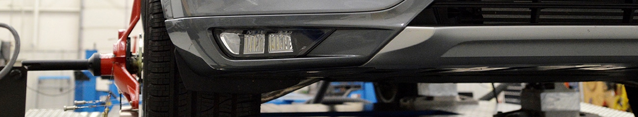
For braking (force at the tire contact), the brakes are applied and force is driven in at the tire contact while the chassis is held fixed.
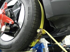
For acceleration or regen braking, the brakes are off. Longitudinal force may be reacted in one of two ways: If it is feasible to lock the transmission, the force may be reacted in the transmission through the driveshafts. But often it’s not feasible to lock the transmission. In those cases, straps are used on the tires. By strapping the tire to the pad with the brakes off, it shifts the point of force application to the wheel center.
Suspension behavior is often quite different, comparing force at the tire contact vs. force at the wheel center, as in the example below:
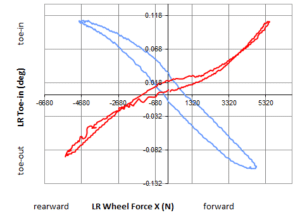
In the above graph, the blue line is braking (force at tire contact), the red line is force at the wheel center. As you can see, by careful design of geometry and selection of bushing stiffnesses, you can achieve compliance toe-in under both braking and acceleration.
With longitudinal compliance, it’s important to evaluate both force at the tire contact and force at the wheel center, to get a complete picture of suspension behavior.
Testing Tip #7: Use K&C to optimize inside the bounds of a spec racing class.
Race engineers in spec racing classes, or in classes where the car is homologated, often don’t see the benefit of K&C testing. The typical thought process is that they can’t make changes to the car and therefore this information is of little value to them. We can tell you from experience that nothing could be further from the truth. In fact, the more constrained you are by the rules, the more important this data will be.
Consider, even though rules might prevent you from changing things like pick-up point locations, there are still changes you can make. What about ride height? How does that impact roll center heights front and rear? How does it impact anti-dive and anti-squat? How much Ackerman do you have and is it pro or anti? What about steer compliance and camber compliance? Is one end of the car significantly weaker than the other? Are there specific problem areas in the suspension?
While you may not be able to solve these problems completely within the constraints of the rules, knowing about them will allow you to more effectively tune around them and understand what you are doing and why. And this knowledge will give you the upper hand over your competitors who would rather remain in the dark about what their suspension is really doing.
K&C Tip #6: Test at different loading conditions.
Measurement of suspension compliance under load is of critical importance to engineers involved in design, development, and simulation. Parameters such as camber and steer and how they change under lateral and longitudinal loading are of critical importance to vehicle handling and performance. Yet another factor that impacts suspension compliance is the vertical loading condition. As such, it is important to measure compliance at all the vertical loading conditions of interest.
What impact does vertical loading have on compliance?
Vertical loading affects compliance in a number of ways. A different vertical load corresponds to a different suspension position, which can result in different compliance. This is especially significant on cars with very short virtual swing arms (either front view or side view). In those cases, compliance can be dramatically different. Another issue occurs on cars with bump stops. Compliance and jacking force can be very different when a car is riding on bump stops compared to a position where a bump stop is not engaged. Even without these factors, all else being equal, you will typically see less camber and steer compliance at higher vertical loading. So be sure to do compliance tests at the vertical loading condition(s) that make sense for your application.
Testing Tip #5: Use on-vehicle sensors.
On-vehicle sensors such as damper (shock) pots and load cells are commonly used on race cars, and can be utilized in K&C testing too. In fact, the on-vehicle sensors are often the only thing you have to correlate data measured on-track with data measured on the K&C rig.
With 26 extra analog channels available, Morse Measurements makes it easy to acquire the signal from your sensors directly into the K&C data acquisition system, which puts that information in the K&C test file with the rest of your K&C data. There are just a few things you need to do in advance to make this successful. First, build jumper cables to connect your sensors to the on-rig Deutsch connector. This connection provides excitation voltage and measures the output signal.
Next, make sure all of your sensor output signals are amplified. The data acquisition system on the K&C rig can read +/-10 V, but it does not have the resolution to read unamplified, millivolt signals. Lastly, provide a calibration to relate the output voltage to the desired measurement, such as load or displacement. These may be a linear gain and offset, or you can provide a more complex relationship. Output data will be provided in the correct, calibrated engineering unit per the calibration you provide.
If you discover a problem with the calibration later, all is not lost. The raw output voltage from the sensor is also provided in the K&C data files, so it’s easy to apply a new calibration, if required.
Testing Tip #4: Use K&C and CMM to validate a kinematic model.
K&C measurements are great for understanding the behavior of your suspension and identifying areas for improvement. However, this data doesn’t directly tell you what changes to make to get the behavior you want. To help with that task, engineers will often rely on suspension kinematic models. Such models are built based on the physical locations of suspension hard points and typically assume rigid body motion. The Morse Measurements CMM service will give you these points.
Testing Tip #3: Understand how to measure roll centers.
Roll centers and corresponding virtual swing arm geometry are important properties of a suspension which can be measured on the K&C rig. Though there is much folklore surrounding “roll centers,” we endeavor here to describe the two different ways to make this measurement on the K&C rig: kinematic and force-based.
For independent suspensions, the kinematic approach measures geometric motion of the wheel relative to the chassis in a vertical bounce test. The rate of change of camber with respect to wheel travel gives us the virtual swing arm length. Lateral motion of the tire contact in bounce (scrub motion) gives us the virtual swing arm angle. These values are then used to determine instant center positions and kinematic roll center height and lateral offset. Further, the kinematic roll center height of an individual corner is reported by projecting from the geometric tire contact point to the centerline of the vehicle. Note that the roll center height and virtual swing arm geometry are calculated based on wheel motion, without measurement of actual suspension hard points.
In the force-based approach, lateral force is applied at the tire contact and the change in vertical force is measured. This change in vertical force with lateral force is commonly referred to as jacking force. The slope of this jacking force curve gives an angle that is analogous to the virtual swing arm angle. This force-based angle we call the force anti-roll angle. By projecting from the tire center of pressure to the centerline of the vehicle along this angle, we are able to determine a force-based roll center height at each corner of the car. This method works with any suspension type (independent, solid axle, twist beam, etc).
So, which method is correct? That depends on your application. If you are trying to correlate a kinematic model of the suspension, you should look at the kinematic roll center heights. These should be close to rigid body kinematics, but often vary due to vertical force compliance effects. If you want to better understand the behavior of the car on-road or on-track, the force-based roll center height is more appropriate. This is because the car responds to forces and knows nothing of the kinematic geometry you or its designer have built into it. It only knows the forces resultant from that geometry.
Do the two methods give the same answer?
Generally, the force-based and kinematic roll center heights are similar, but not the same. The trend is for the force-based roll center height to be lower than the kinematic. This is understandable because in most K&C tests there is a large compliant member in the system, namely the tire. Compression and lateral deflection of the tire with jacking force will tend to reduce the measured jacking force, leading to a lower anti-roll angle and a lower force-based roll center height. In addition, for cars with a lot of static camber and/or a lot camber gain, there can be significant differences between the geometric tire contact point and the tire center of pressure. This will lead to different “roll center” heights because we are projecting from a different tire contact point. The kinematic method uses the geometric tire contact point while the force-based uses the measured center of pressure position of the tire.
But how can you be sure that the kinematic model you built is an accurate representation of the real suspension?
The best way is to have K&C data to which you can directly compare the kinematic model. Will the model match the K&C measurements exactly? Certainly not. Even if the model was otherwise perfect, rigid body kinematic models do not account for component deflection (the Compliance in K&C). Such compliance occurs as a result of loading in any direction, including vertical loading.
If possible, you can run a K&C test without springs in the car. This will give you true kinematics without vertical force compliance effects. Such data should match the kinematic model more closely.
The K&C test and the CMM can be accomplished in one trip to Morse Measurements, giving you all the information you need to build a validated suspension kinematic model.
Testing Tip #2: If you’re changing springs, have a plan for limiting droop.
Part of the test procedure in K&C testing at Morse Measurements involves lifting the car off the pads, zeroing the load cells, and resetting pad positions. This is done before the start of each test. For stock cars, this means you should have shocks on the front of the car and shocks and / or droop limiting chains on the rear axle. For all cars, you should be sure that when the car is picked up, the springs don’t have the opportunity to fall out or misalign. Springs that require baby sitting on each vehicle lift slow down your K&C test. Further, springs that are not seated properly lead to incorrect measurements, general dismay, and sad pandas.
So what happens when you want to change springs on the K&C rig?
For stock cars, the procedure is to disconnect shocks and chains (as well as any vulnerable linear pots, which make poor droop limiting devices), then lift the vehicle very high such that springs can (usually) be removed. Once springs are removed and the new springs are in place, the car is brought back down to static ride height. At this point, shocks and any droop limiting chains and linear pots are reinstalled.
For sports cars, open wheel, and prototype cars, we can touch the tires down on the pads such that the coil-over units may be removed. Some sports cars may require the wheels to be removed to change springs. This is more time consuming, but also may be accomplished on the K&C rig.
After springs are installed and droop limiting is in place, we go to a “micro bounce” test to set / confirm the vertical load. This is roughly equivalent to setting corner weights on the ground, except that each corner of the car is independent of the others, making it easier to hit your desired targets. The large, live weight display projected on the wall at Morse Measurements makes this easy! By the way, the micro bounce test cycles the car up and down over a very small displacement such that we overcome suspension friction and can measure vertical load in the middle of the friction loop. Otherwise we will always be measuring either one side or the other of what can be a very significant friction loop, leading to inaccuracies in vertical load.
Testing Tip #1: Think in terms of ride height, not corner weight.
Ideally, race cars should be setup for a K&C test as if going on-track. That is, setup to the correct ride height, weight, alignment, etc. But sometimes, it isn’t feasible to set everything properly. When that happens, the ride height is the most important thing to set correct. This is because on the K&C rig, the car is clamped or bolted down at a known height. The machine will then return to this ride height all day. And it will do so independent of weight. That doesn’t sound like much of a statement on the surface, but it is exactly the opposite of what happens in real life. On the ground, the car will always weigh the same, but the ride height will vary based on spring pre-load, suspension friction, dampers, etc.
This can take some time to get used to. Another oddity related to clamping the car to the K&C center table is that setting corner weights is easier in that setting one corner has little or no influence on the other corners of the car. Again, different than on the ground. So if the car is at the correct height, and clamped to the center table at that height, changes to spring pre-load, push rod length, etc. may be done after clamping to achieve the correct corner weights, with no resultant change in height. You are then able to test the car at the correct height and the correct weight.
It’s important to think about ride height and corner weights before your test, and come in with a plan on how you will set and verify ride height and corner weights.
There’s So Much More
There’s a lot more to planning and preparing for an optimized K&C test session. We want to work with you to make sure you get what you need out of your test. Contact us with questions or for more information.
Want to read more? Check out this article about defining K&C testing, and this one about planning a K&C test session.
Top Tips Get the Most Out of Your K&C Test
Like anything else in life, the more experience you have with K&C testing, the better you get at it. And while there is no substitute for experience, we can provide you various tips, hints, and suggestions for how to utilize K&C test data and how to get the most out of your test day. Think through these K&C testing tips to get the most out of your test.
Testing Tip #8: Know Your Longitudinal Compliance Test!
Traditional compliance testing is a big part of Kinematics & Compliance (K&C) testing. When we say “compliance,” we are referring to the inverse of stiffness, not compliance with regulations (for example).
When applying force in the longitudinal direction, you have the choice of applying force at the tire contact (at the ground), or at the wheel center. Longitudinal force at the tire contact is representative of what happens under braking. Longitudinal force at the wheel center is representative of acceleration (forward direction) or regenerative braking on hybrid and electric cars (backwards direction).
How is this done in a K&C test?
For braking (force at the tire contact), the brakes are applied and force is driven in at the tire contact while the chassis is held fixed.
For acceleration or regen braking, the brakes are off. Longitudinal force may be reacted in one of two ways: If it is feasible to lock the transmission, the force may be reacted in the transmission through the driveshafts. But often it’s not feasible to lock the transmission. In those cases, straps are used on the tires. By strapping the tire to the pad with the brakes off, it shifts the point of force application to the wheel center.
Suspension behavior is often quite different, comparing force at the tire contact vs. force at the wheel center, as in the example below:
In the above graph, the blue line is braking (force at tire contact), the red line is force at the wheel center. As you can see, by careful design of geometry and selection of bushing stiffnesses, you can achieve compliance toe-in under both braking and acceleration.
With longitudinal compliance, it’s important to evaluate both force at the tire contact and force at the wheel center, to get a complete picture of suspension behavior.
Testing Tip #7: Use K&C to optimize inside the bounds of a spec racing class.
Race engineers in spec racing classes, or in classes where the car is homologated, often don’t see the benefit of K&C testing. The typical thought process is that they can’t make changes to the car and therefore this information is of little value to them. We can tell you from experience that nothing could be further from the truth. In fact, the more constrained you are by the rules, the more important this data will be.
Consider, even though rules might prevent you from changing things like pick-up point locations, there are still changes you can make. What about ride height? How does that impact roll center heights front and rear? How does it impact anti-dive and anti-squat? How much Ackerman do you have and is it pro or anti? What about steer compliance and camber compliance? Is one end of the car significantly weaker than the other? Are there specific problem areas in the suspension?
While you may not be able to solve these problems completely within the constraints of the rules, knowing about them will allow you to more effectively tune around them and understand what you are doing and why. And this knowledge will give you the upper hand over your competitors who would rather remain in the dark about what their suspension is really doing.
K&C Tip #6: Test at different loading conditions.
Measurement of suspension compliance under load is of critical importance to engineers involved in design, development, and simulation. Parameters such as camber and steer and how they change under lateral and longitudinal loading are of critical importance to vehicle handling and performance. Yet another factor that impacts suspension compliance is the vertical loading condition. As such, it is important to measure compliance at all the vertical loading conditions of interest.
What impact does vertical loading have on compliance?
Vertical loading affects compliance in a number of ways. A different vertical load corresponds to a different suspension position, which can result in different compliance. This is especially significant on cars with very short virtual swing arms (either front view or side view). In those cases, compliance can be dramatically different. Another issue occurs on cars with bump stops. Compliance and jacking force can be very different when a car is riding on bump stops compared to a position where a bump stop is not engaged. Even without these factors, all else being equal, you will typically see less camber and steer compliance at higher vertical loading. So be sure to do compliance tests at the vertical loading condition(s) that make sense for your application.
Testing Tip #5: Use on-vehicle sensors.
On-vehicle sensors such as damper (shock) pots and load cells are commonly used on race cars, and can be utilized in K&C testing too. In fact, the on-vehicle sensors are often the only thing you have to correlate data measured on-track with data measured on the K&C rig.
With 26 extra analog channels available, Morse Measurements makes it easy to acquire the signal from your sensors directly into the K&C data acquisition system, which puts that information in the K&C test file with the rest of your K&C data. There are just a few things you need to do in advance to make this successful. First, build jumper cables to connect your sensors to the on-rig Deutsch connector. This connection provides excitation voltage and measures the output signal.
Next, make sure all of your sensor output signals are amplified. The data acquisition system on the K&C rig can read +/-10 V, but it does not have the resolution to read unamplified, millivolt signals. Lastly, provide a calibration to relate the output voltage to the desired measurement, such as load or displacement. These may be a linear gain and offset, or you can provide a more complex relationship. Output data will be provided in the correct, calibrated engineering unit per the calibration you provide.
If you discover a problem with the calibration later, all is not lost. The raw output voltage from the sensor is also provided in the K&C data files, so it’s easy to apply a new calibration, if required.
Testing Tip #4: Use K&C and CMM to validate a kinematic model.
K&C measurements are great for understanding the behavior of your suspension and identifying areas for improvement. However, this data doesn’t directly tell you what changes to make to get the behavior you want. To help with that task, engineers will often rely on suspension kinematic models. Such models are built based on the physical locations of suspension hard points and typically assume rigid body motion. The Morse Measurements CMM service will give you these points.
But how can you be sure that the kinematic model you built is an accurate representation of the real suspension?
The best way is to have K&C data to which you can directly compare the kinematic model. Will the model match the K&C measurements exactly? Certainly not. Even if the model was otherwise perfect, rigid body kinematic models do not account for component deflection (the Compliance in K&C). Such compliance occurs as a result of loading in any direction, including vertical loading.
If possible, you can run a K&C test without springs in the car. This will give you true kinematics without vertical force compliance effects. Such data should match the kinematic model more closely.
The K&C test and the CMM can be accomplished in one trip to Morse Measurements, giving you all the information you need to build a validated suspension kinematic model.
Testing Tip #3: Understand how to measure roll centers.
Roll centers and corresponding virtual swing arm geometry are important properties of a suspension which can be measured on the K&C rig. Though there is much folklore surrounding “roll centers,” we endeavor here to describe the two different ways to make this measurement on the K&C rig: kinematic and force-based.
For independent suspensions, the kinematic approach measures geometric motion of the wheel relative to the chassis in a vertical bounce test. The rate of change of camber with respect to wheel travel gives us the virtual swing arm length. Lateral motion of the tire contact in bounce (scrub motion) gives us the virtual swing arm angle. These values are then used to determine instant center positions and kinematic roll center height and lateral offset. Further, the kinematic roll center height of an individual corner is reported by projecting from the geometric tire contact point to the centerline of the vehicle. Note that the roll center height and virtual swing arm geometry are calculated based on wheel motion, without measurement of actual suspension hard points.
In the force-based approach, lateral force is applied at the tire contact and the change in vertical force is measured. This change in vertical force with lateral force is commonly referred to as jacking force. The slope of this jacking force curve gives an angle that is analogous to the virtual swing arm angle. This force-based angle we call the force anti-roll angle. By projecting from the tire center of pressure to the centerline of the vehicle along this angle, we are able to determine a force-based roll center height at each corner of the car. This method works with any suspension type (independent, solid axle, twist beam, etc).
So, which method is correct? That depends on your application. If you are trying to correlate a kinematic model of the suspension, you should look at the kinematic roll center heights. These should be close to rigid body kinematics, but often vary due to vertical force compliance effects. If you want to better understand the behavior of the car on-road or on-track, the force-based roll center height is more appropriate. This is because the car responds to forces and knows nothing of the kinematic geometry you or its designer have built into it. It only knows the forces resultant from that geometry.
Do the two methods give the same answer?
Generally, the force-based and kinematic roll center heights are similar, but not the same. The trend is for the force-based roll center height to be lower than the kinematic. This is understandable because in most K&C tests there is a large compliant member in the system, namely the tire. Compression and lateral deflection of the tire with jacking force will tend to reduce the measured jacking force, leading to a lower anti-roll angle and a lower force-based roll center height. In addition, for cars with a lot of static camber and/or a lot camber gain, there can be significant differences between the geometric tire contact point and the tire center of pressure. This will lead to different “roll center” heights because we are projecting from a different tire contact point. The kinematic method uses the geometric tire contact point while the force-based uses the measured center of pressure position of the tire.
Testing Tip #2: If you’re changing springs, have a plan for limiting droop.
Part of the test procedure in K&C testing at Morse Measurements involves lifting the car off the pads, zeroing the load cells, and resetting pad positions. This is done before the start of each test. For stock cars, this means you should have shocks on the front of the car and shocks and / or droop limiting chains on the rear axle. For all cars, you should be sure that when the car is picked up, the springs don’t have the opportunity to fall out or misalign. Springs that require baby sitting on each vehicle lift slow down your K&C test. Further, springs that are not seated properly lead to incorrect measurements, general dismay, and sad pandas.
So what happens when you want to change springs on the K&C rig?
For stock cars, the procedure is to disconnect shocks and chains (as well as any vulnerable linear pots, which make poor droop limiting devices), then lift the vehicle very high such that springs can (usually) be removed. Once springs are removed and the new springs are in place, the car is brought back down to static ride height. At this point, shocks and any droop limiting chains and linear pots are reinstalled.
For sports cars, open wheel, and prototype cars, we can touch the tires down on the pads such that the coil-over units may be removed. Some sports cars may require the wheels to be removed to change springs. This is more time consuming, but also may be accomplished on the K&C rig.
After springs are installed and droop limiting is in place, we go to a “micro bounce” test to set / confirm the vertical load. This is roughly equivalent to setting corner weights on the ground, except that each corner of the car is independent of the others, making it easier to hit your desired targets. The large, live weight display projected on the wall at Morse Measurements makes this easy! By the way, the micro bounce test cycles the car up and down over a very small displacement such that we overcome suspension friction and can measure vertical load in the middle of the friction loop. Otherwise we will always be measuring either one side or the other of what can be a very significant friction loop, leading to inaccuracies in vertical load.
Testing Tip #1: Think in terms of ride height, not corner weight.
Ideally, race cars should be setup for a K&C test as if going on-track. That is, setup to the correct ride height, weight, alignment, etc. But sometimes, it isn’t feasible to set everything properly. When that happens, the ride height is the most important thing to set correct. This is because on the K&C rig, the car is clamped or bolted down at a known height. The machine will then return to this ride height all day. And it will do so independent of weight. That doesn’t sound like much of a statement on the surface, but it is exactly the opposite of what happens in real life. On the ground, the car will always weigh the same, but the ride height will vary based on spring pre-load, suspension friction, dampers, etc.
This can take some time to get used to. Another oddity related to clamping the car to the K&C center table is that setting corner weights is easier in that setting one corner has little or no influence on the other corners of the car. Again, different than on the ground. So if the car is at the correct height, and clamped to the center table at that height, changes to spring pre-load, push rod length, etc. may be done after clamping to achieve the correct corner weights, with no resultant change in height. You are then able to test the car at the correct height and the correct weight.
It’s important to think about ride height and corner weights before your test, and come in with a plan on how you will set and verify ride height and corner weights.
There’s So Much More
There’s a lot more to planning and preparing for an optimized K&C test session. We want to work with you to make sure you get what you need out of your test. Contact us with questions or for more information.
Want to read more? Check out this article about defining K&C testing, and this one about planning a K&C test session.
Call Now: 704.638.6515
Call Now:
704.638.6515
![]()
![]()
![]()
1163 Speedway Blvd.,
Salisbury, NC 28146
Phone: 704.638.6515
Fax: 704.638.6516
Info@MorseMeasurements.com
© 2025 Morse Measurements | Powered by Miller Davis
![]()
![]()
![]()
1163 Speedway Blvd., Salisbury, NC 28146
Phone: 704.638.6515
Fax: 704.638.6516
Info@MorseMeasurements.com
© 2025 Morse Measurements | Powered by Miller Davis